In industrial engineering, failure is not just expensive. It is disruptive, dangerous, and often preventable. Structural cracks, unexpected deformation, thermal stress damage, and fatigue fractures can shut down operations and compromise safety. The smartest way to avoid these risks is to detect them long before fabrication begins. That is where mechanical 3D modeling combined with Finite Element Analysis becomes indispensable.
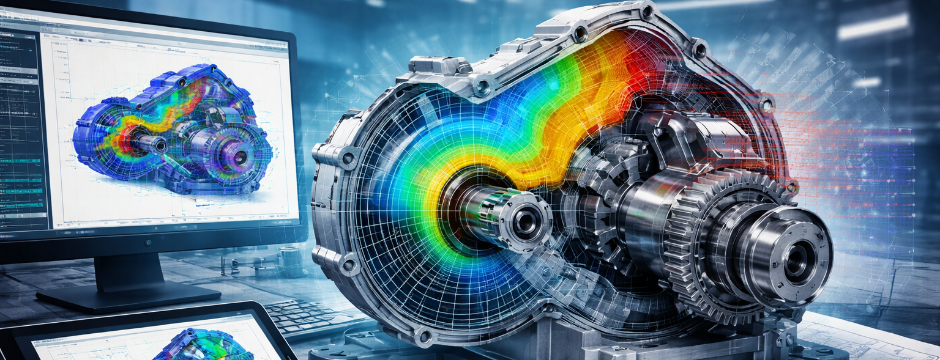
Finite Element Analysis, commonly known as FEA, allows engineers to simulate real-world forces on digital models before any material is cut, welded, or assembled. When integrated into mechanical 3D modeling and drafting for industrial projects, FEA transforms a static design into a tested, performance-validated engineering solution. Instead of guessing how a structure might behave, engineers can see it in action under realistic load conditions.
What Is Finite Element Analysis
Finite Element Analysis is a computational method used to predict how a component or system responds to external forces, pressure, vibration, heat, and other physical effects. The model is divided into thousands or even millions of small elements. Each element is analyzed mathematically to understand how it reacts to applied conditions.
The power of FEA lies in its ability to break down complex geometries into manageable sections. This allows engineers to evaluate stress distribution, strain levels, deflection, temperature gradients, and fatigue behavior with impressive accuracy.
When FEA is embedded within mechanical 3D modeling workflows, the result is not just a visually accurate model. It becomes a performance-tested structure ready for fabrication.
Why Structural Failures Occur in Industrial Projects
Structural failures typically happen for predictable reasons. Many of them can be traced back to design-stage oversights:
- Underestimated load conditions
- Inadequate material thickness
- Improper weld placement
- Thermal expansion stress
- Vibration resonance
- Fatigue from cyclic loading
- Poor support distribution
In large industrial facilities such as process plants, hydrogen systems, waste-to-energy installations, and heavy mechanical assemblies, these factors interact in complex ways. Without simulation, it is nearly impossible to foresee all performance risks.
Mechanical 3D modeling allows engineers to visualize geometry and assembly relationships. FEA adds the missing layer of structural intelligence by showing how those geometries behave under operational conditions.
The Integration of FEA into Mechanical 3D Modeling
Modern engineering software integrates FEA directly within the mechanical 3D modeling environment. This seamless workflow ensures that validation happens early and continuously throughout the design process.
Here is how the integration typically works:
- A detailed 3D model is created.
- Material properties are assigned to each component.
- Load cases are defined, including weight, pressure, thermal input, vibration, and environmental forces.
- Boundary conditions are established to simulate supports and constraints.
- The model is meshed into finite elements.
- The solver calculates stress, displacement, and other response metrics.
The results are visualized as stress maps, deformation plots, and temperature gradients. Engineers can immediately identify high-stress regions, weak joints, and areas susceptible to fatigue.
This combination of mechanical 3D modeling and performance simulation dramatically reduces uncertainty before fabrication.
Key Applications of FEA in Industrial Mechanical Design
Structural Load Analysis
Industrial frames, pressure vessels, structural supports, and equipment housings must withstand static and dynamic loads. FEA identifies stress concentrations that could lead to cracking or permanent deformation.
By refining geometry and adjusting thickness where necessary, engineers ensure that the structure meets safety factors without excessive material usage.
Thermal Stress Evaluation
High-temperature systems such as reactors, heat exchangers, combustion units, and hydrogen processing equipment experience thermal expansion and contraction. Uneven temperature distribution can cause distortion or stress buildup.
Finite Element Analysis simulates these thermal conditions during the mechanical 3D modeling stage. Engineers can modify expansion joints, select appropriate materials, and adjust clearances to prevent long-term damage.
Vibration and Fatigue Testing
Rotating machinery, conveyors, pumps, and turbines are exposed to repetitive loads. Even moderate stress levels can cause fatigue over time.
FEA allows motion and fatigue simulations that predict lifecycle performance. This is critical for avoiding unexpected shutdowns due to mechanical failure.
Fluid Structure Interaction
In process systems where fluids exert pressure on mechanical components, structural integrity must be carefully validated. Tanks, ducts, piping, and combustion chambers experience variable pressure loads.
Simulation within mechanical 3D modeling environments evaluates how fluid pressure interacts with structural supports and shell thickness.
Cost Impact of Early Failure Detection
The cost difference between correcting a design digitally and correcting it after fabrication is enormous.
Design-stage modifications typically involve:
- Adjusting geometry
- Modifying thickness
- Adding reinforcement
- Repositioning supports
Post-fabrication corrections often involve:
- Rework and welding
- Material replacement
- Project delays
- Site modifications
- Safety risks
Mechanical 3D modeling and drafting for industrial projects combined with FEA prevents expensive surprises. It reduces change orders and keeps projects on schedule.
Improving Collaboration Through 3D Design Visualization
Engineering is rarely a solo activity. Designers, structural engineers, automation teams, procurement managers, and fabrication partners must collaborate effectively.
3D design visualization plays a major role in aligning these stakeholders. When FEA results are layered onto 3D models, decision makers can clearly see why design adjustments are necessary. Stress hotspots and deformation zones are visually intuitive.
This improves communication between engineering and fabrication teams. It also strengthens client confidence by demonstrating that the design has been performance-tested.
Material Optimization and Sustainability
Overdesign increases material cost and weight. Underdesign increases risk. FEA helps find the right balance.
By analyzing stress distribution within a mechanical 3D modeling environment, engineers can remove unnecessary material from low-stress areas and reinforce only where required. This optimized approach reduces steel consumption, lowers fabrication costs, and improves sustainability metrics.
In industries moving toward energy efficiency and carbon reduction, structural optimization through simulation supports long-term environmental goals.
Compliance and Safety Validation
Many industrial projects must comply with structural and safety standards. Pressure vessel codes, load-bearing regulations, seismic design requirements, and thermal safety limits must all be validated.
FEA provides documented engineering evidence that a design meets required safety factors. This documentation supports regulatory approval and operational readiness.
When mechanical 3D modeling integrates compliance-focused simulation, the project is prepared not only for fabrication but also for inspection and audit processes.
TechUrja’s Approach to Simulation-Driven Design
At TechUrja, we integrate Finite Element Analysis directly into our mechanical 3D modeling workflows to ensure every design is performance-validated before fabrication. Our team combines structural analysis expertise with real-world industrial experience across energy systems, process plants, and advanced material projects.
We do not treat modeling as a drafting exercise. Our approach to mechanical 3D modeling and drafting for industrial projects focuses on structural integrity, operational safety, and long-term reliability. By applying stress analysis, thermal evaluation, and fatigue testing early in the design cycle, we help our clients minimize risk, control costs, and improve system durability.
Our emphasis on 3D design visualization ensures that simulation insights are clearly communicated across stakeholders. This strengthens collaboration between engineering, fabrication, and site teams while improving project execution outcomes.
Conclusion
Structural failures rarely happen without warning. The warning signs exist in the physics of the design. Finite Element Analysis reveals those warning signs before fabrication begins.
When combined with mechanical 3D modeling, FEA transforms industrial design from a geometric exercise into a performance-tested engineering solution. It protects budgets, safeguards operations, and ensures that systems function as intended in real-world conditions.
For industrial organizations seeking reliability, compliance, and efficiency, simulation-driven mechanical 3D modeling is not optional. It is essential for building durable, safe, and high-performance systems that stand the test of time.
Frequently Asked Questions
1. What is the role of Finite Element Analysis in mechanical 3D modeling?
Finite Element Analysis evaluates how a digitally created component or system behaves under real-world conditions such as load, pressure, heat, and vibration. When integrated into mechanical 3D modeling, FEA allows engineers to detect stress concentrations, deformation risks, and fatigue issues before fabrication begins. This ensures the final design is structurally sound and performance-ready.
2. How does FEA reduce fabrication costs in industrial projects?
FEA identifies structural weaknesses and performance risks during the design phase. Making changes in a digital model is significantly more cost-effective than correcting errors after fabrication or installation. By refining geometry, adjusting material thickness, and reinforcing critical areas early, companies reduce rework, downtime, and unexpected site modifications.
3. Can Finite Element Analysis improve regulatory compliance?
Yes. FEA provides documented proof that a design meets required safety factors and engineering standards. Stress calculations, thermal analysis results, and load simulations support compliance with structural codes, pressure vessel standards, and industrial safety regulations. This strengthens audit readiness and simplifies approval processes.
4. What types of industrial systems benefit most from FEA in mechanical 3D modeling?
High-load and high-temperature systems benefit significantly from FEA. These include pressure vessels, heat exchangers, hydrogen storage units, waste-to-energy systems, rotating equipment, structural frames, and modular plant assemblies. Any system exposed to thermal stress, vibration, or cyclic loading should undergo simulation-based validation.
5. Is FEA necessary for small-scale industrial components?
Even smaller components can experience fatigue, stress concentration, or deformation over time. FEA is especially important when components operate under repetitive loads, elevated temperatures, or tight tolerance requirements. Applying simulation during mechanical 3D modeling ensures long-term durability, even in compact assemblies.